You're reading the documentation of the v0.6. For the latest released version, please have a look at v1.2.
Components
Overview
Name |
Object Name |
Representation |
Representation |
Unitary Matrix |
|---|---|---|---|---|
|
|
|
\(\left[\begin{matrix}e^{i \phi_{a}} \cos{\left(\theta \right)} & i e^{i \phi_{b}} \sin{\left(\theta \right)}\\i e^{i \left(\phi_{a} - \phi_{b} + \phi_{d}\right)} \sin{\left(\theta \right)} & e^{i \phi_{d}} \cos{\left(\theta \right)}\end{matrix}\right]\) |
|
|
|
|
\(\left[\begin{matrix}e^{i \phi}\end{matrix}\right]\) |
|
|
|
|
\(\left[\begin{matrix}0 & 1\\1 & 0\end{matrix}\right]\) |
|
|
|
|
\(\left[\begin{matrix}i \sin{\left(\delta \right)} \cos{\left(2 \xi \right)} + \cos{\left(\delta \right)} & i \sin{\left(\delta \right)} \sin{\left(2 \xi \right)}\\i \sin{\left(\delta \right)} \sin{\left(2 \xi \right)} & - i \sin{\left(\delta \right)} \cos{\left(2 \xi \right)} + \cos{\left(\delta \right)}\end{matrix}\right]\) |
|
|
|
|
\(\left[\begin{matrix}0 & 0 & 1 & 0\\0 & 1 & 0 & 0\\1 & 0 & 0 & 0\\0 & 0 & 0 & 1\end{matrix}\right]\) |
|
|
|
|
\(\left[\begin{matrix}\cos{\left(\delta \right)} & \sin{\left(\delta \right)}\\- \sin{\left(\delta \right)} & \cos{\left(\delta \right)}\end{matrix}\right]\) |
|
|
|
|
N/A |
Description
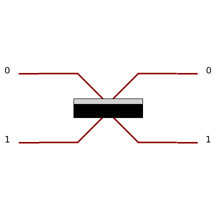
Beam Splitter
Beam splitters couple two spatial modes together, implementing the following unitary acting on \(\ket{1,0}\) and \(\ket{0,1}\):
\(\left[\begin{matrix} \cos{\left(\theta \right)} & i e^{i \phi} \sin{\left(\theta \right)}\\i e^{-i \phi} \sin{\left(\theta \right)} & \cos{\left(\theta \right)}\end{matrix}\right]\)
and are parametrized usually by angles \(\theta\) and \(\phi\), where \(\theta\) relates to the reflectivity and \(\phi\) corresponds to a relative phase between the modes. Beam splitters exist as bulk, fibered and on-chip components.
It is also possible to use \(R\) parameter with the following relationship: \(cos \theta= \sqrt{1-R}\).
In the phys library the beam splitters are described by four parameters: \(\theta, \phi_a, \phi_b, \phi_c\),
where \(\theta\) and \(\phi_b\) correspond to the above \(\theta\) and \(\phi\). \(\phi_a\)
and \(\phi_c\) are additional phases that can be observed in actual devices.
These can that can be achieved in practice with the simplified unitary (present in the symb library) by using phase
shifters at the input and output of the beamsplitter and thus are included for compactness directly into the component.
To create a beam splitter object from the phys library:
>>> import perceval.lib.phys as phys
>>> beam_splitter = phys.BS()
By default
theta is \(\pi/4\),
phi_a is \(0\),
phi_b is \(3\pi/2\),
phi_d is \(\pi\).
These values can be modified by using optional parameters when creating a BS object.
In the symb library:
>>> import perceval.lib.symb as symb
>>> beam_splitter = symb.BS()
Only parameters theta and phi can be specified when using the symb library.
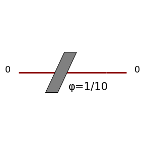
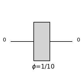
Phase Shifter
A phase shifter adds a phase \(\phi\) on a spatial mode, which corresponds to a Z rotation in the Bloch sphere.
The definition of a phase shifter uses the same (non-optional) parameter phi in both libraries symb and phys.
To create a phase shifter PS object:
>>> import perceval.lib.phys as phys
>>> phase_shifter = phys.PS(sp.pi/2) # phi = pi/2
or:
>>> import perceval.lib.symb as symb
>>> phase_shifter = symb.PS(sp.pi/2)
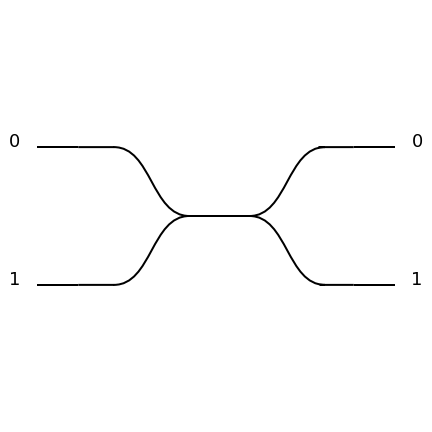
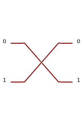
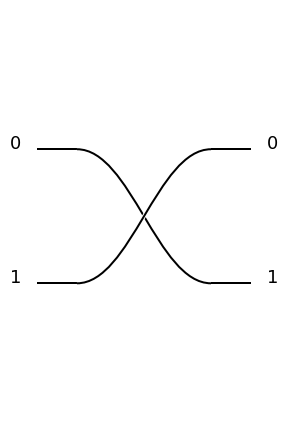
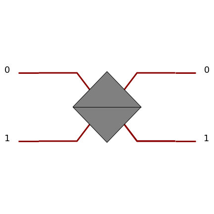
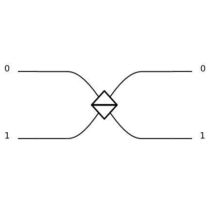
Permutation
A permutation exchanges two spatial modes, sending \(\ket{0,1}\) to \(\ket{1,0}\) and vice-versa.
To create a permutation PERM object corresponding to the above example:
>>> import perceval.lib.symb as symb
>>> permutation = symb.PERM([1,0])
or:
>>> import perceval.lib.phys as phys
>>> permutation = phys.PERM([1,0])
More generally one can define Permutation on an arbitrary number of modes. The permutation should be described by a list of integers from 0 to \(l-1\), where \(l\) is the length of the list. The \(k\) th spatial input mode is sent to the spatial output mode corresponding to the \(k\) th value in the list.
For instance the following defines a 4-mode permutation. It matches the first input path (index 0) with the third output path (value 2), the second input path with the fourth output path, the third input path, with the first output path, and the fourth input path with the second output path.
>>> c=phys.PERM([2,3,0,1])
>>> pcvl.pdisplay(c)
>>> pcvl.pdisplay(c.compute_unitary(), output_format="latex")
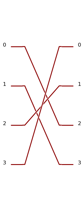
|
\[\begin{split}\left[\begin{matrix}0 & 0 & 1 & 0\\0 & 0 & 0 & 1\\0 & 1 & 0 & 0\\1 & 0 & 0 & 0\end{matrix}\right]\end{split}\]
|
We can do exactly the same with the symb library.
>>> c=symb.PERM([2,3,0,1])
>>> pcvl.pdisplay(c)
>>> pcvl.pdisplay(c.compute_unitary(), output_format="latex")
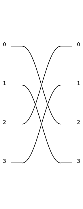
|
\[\begin{split}\left[\begin{matrix}0 & 0 & 1 & 0\\0 & 0 & 0 & 1\\0 & 1 & 0 & 0\\1 & 0 & 0 & 0\end{matrix}\right]\end{split}\]
|
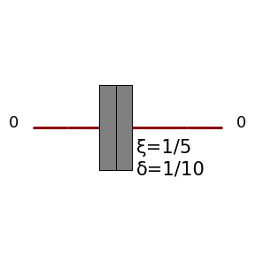
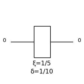
Waveplate
A waveplate acts on the polarisation modes of a single spatial mode. It is described by the following unitary:
\(\delta\) is a parameter proportional to the thickness of the waveplate and \(\xi\) represents the angle of the waveplate’s optical axis in the \(\left\{\ket{H}, \ket{V}\right\}\) plane. Especially important is the case that \(\delta=\pi/2\), known as a half-wave plate, which rotates linear polarisations in the \(\left\{\ket{H}, \ket{V}\right\}\) plane.
Polarizing Beam Splitter
A polarising beam splitter converts a superposition of polarisation modes in a single spatial mode to the corresponding equal-polarisation superposition of two spatial modes,and vice versa, and so in this sense allow us to translate between polarisation and spatial modes. The unitary matrix associated to a polarising beam splitter acting on the tensor product of the spatial mode and the polarisation mode is:
Polarization Rotator
A polarization rotator is an optical device that rotates the polarization axis of a linearly polarized light beam by an angle of choice. Such devices can be based on the Faraday effect, on birefringence, or on total internal reflection. Rotators of linearly polarized light have found widespread applications in modern optics since laser beams tend to be linearly polarized and it is often necessary to rotate the original polarization to its orthogonal alternative.
See https://en.wikipedia.org/wiki/Polarization_rotator for more details.
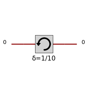
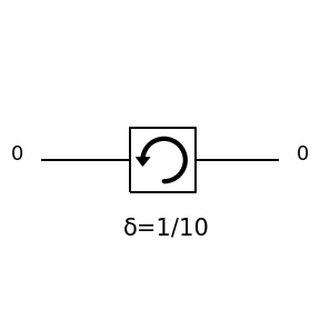
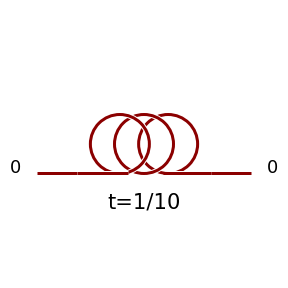
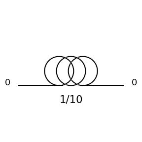
Time Delay
Time Delay is a special component corresponding to a roll of optical fiber making as an effect to delay a photon. Parameter of the Time Delay is the fraction of a period the delay should be.
For instance DT(0.5) will make a delay on the line corresponding to half of a period.