You're reading the documentation of the v1.0. For the latest released version, please have a look at v1.2.
Qiskit converter
Qiskit is an opensource quantum development library. A Qiskit QuantumCircuit can be converted to an equivalent Perceval Processor using QiskitConverter.
Note that this notebook requires the installation of Qiskit (which can be easily done with pip install qiskit). This repository can also be installed with the command: pip install .[Qiskit-bridge] to automatically install Qiskit.
Minimal code
[1]:
import qiskit
from perceval_interop import QiskitConverter
Create a Quantum Circuit (the following is pure Qiskit syntax):
[2]:
qc = qiskit.QuantumCircuit(2)
qc.h(0)
qc.cx(0, 1)
print(qc.draw())
     ┌───┐
q_0: ┤ H ├──■──
     └───┘┌─┴─┐
q_1: ─────┤ X ├
          └───┘
Then convert the Quantum Circuit with Perceval QiskitConvertor
[3]:
qiskit_convertor = QiskitConverter()
perceval_processor = qiskit_convertor.convert(qc)
See also: Qiskit tutorial
Decomposing gate-based circuits
In this section, we show how circuits from Qiskit can be converted into Perceval circuits by taking the example of a simple gate-based circuit producing GHZ states. We then show the translation to a linear optical circuit. We also show the equivalence between the two circuits (gate-based and perceval).
[4]:
from qiskit import QuantumCircuit
from qiskit.quantum_info import Statevector

import perceval as pcvl
from perceval.algorithm import Analyzer, Sampler

from perceval_interop import QiskitConverter
GHZ State generation in Qiskit
We first define the circuit generating GHZ states of 3 qubits with Qiskit. To do so, we first act with a Hadamard gate on qubit 0 to put in superposition of state \(|0\rangle\) and \(|1\rangle\). Then we perform two CNOT gates using qubit 0 as control and qubits 1 and 2 as targets.
[5]:
# Create a Quantum Circuit acting on the q register
qiskit_circuit = QuantumCircuit(3)

# Add a H gate on qubit 0
qiskit_circuit.h(0)

# Add CX (CNOT) gates on control qubit 0 and target qubits 1 and 2
qiskit_circuit.cx(0, 1)
qiskit_circuit.cx(0, 2)

# Draw the circuit
qiskit_circuit.draw()
[5]:
     ┌───┐
q_0: ┤ H ├──■────■──
     └───┘┌─┴─┐  │
q_1: ─────┤ X ├──┼──
          └───┘┌─┴─┐
q_2: ──────────┤ X ├
               └───┘
We display the final state when starting from the input state \(|000\rangle\).
[6]:
# Set the initial state of the simulator to the ground state using from_int
state = Statevector.from_int(0, 2**3)

# Evolve the state by the quantum circuit
state = state.evolve(qiskit_circuit)

#draw using latex
state.draw('latex')
[6]:
Conversion of Qiskit circuit to Perceval
With the use of QiskitConverter, we can transform the Qiskit circuit into a Perceval circuit. It uses 2 modes per qubit and additional modes for ancillary photons to perform deterministically two-qubit gates. Below the first six modes correspond to the three logical qubits (see the Spatial Modes encoding paragraph in the ‘Basics’ section of the Perceval documentation) of the gate-based circuit above.
The other modes are used to successfully implement two-qubit gates via heralding or post-selection. Heralding employs 2 ancillary modes with 1 photon each while post-selection employs 2 empty ancillary modes. With the option use_postselection=True in the method .convert on a QiskitConverter object, every CNOT but the last is implemented with a heralding scheme. Here it
means that it would add \(4\) ancillary modes with \(2+0\) added photons. The option use_postselection=False only implements heralded CNOTs. Here it would mean \(4\) ancillary modes with \(2+2\) added photons. Note: the use_postselection option is True by default.
Sometimes, the structure of a given circuit allows the converter to use more than one post-selected two-qubit gate in a single circuit. This is the case here.
[7]:
qiskit_converter = QiskitConverter(backend_name="Naive")
quantum_processor = qiskit_converter.convert(qiskit_circuit, use_postselection=True)
pcvl.pdisplay(quantum_processor, recursive=True)
[7]:

With this converted circuit, we can now check that the resulting state is the same as before the conversion. By default, the input is the logical state \(|000\rangle_L\). Note that where Qiskit displays state in the order \(|q_2q_1q_0\rangle_L\), Perceval uses the reverse order \(|q_0q_1q_2\rangle_L\), but still shown as Fock states. Here, it doesn’t change anything since we end with only \(|000\rangle_L\) and \(|111\rangle_L\) states.
[8]:
# Not necessary here
quantum_processor.with_input(pcvl.LogicalState([0,0,0]))

sampler = Sampler(quantum_processor)

output_distribution = sampler.probs()["results"]
pcvl.pdisplay(output_distribution, precision=1e-2, max_v = 4)
| state | probability |
|---|---|
| |0,1,0,1,0,1> | 1/2 |
| |1,0,1,0,1,0> | 1/2 |
This circuit can now be converted using a general interferometer decomposition so it can be implemented on a generic photonic chip.
[9]:
# use quantum_processor
u = quantum_processor.linear_circuit().compute_unitary(use_symbolic=False)
[10]:
ub = (pcvl.Circuit(2)
      // pcvl.BS(theta=pcvl.Parameter("theta"))
      // (0, pcvl.PS(phi=pcvl.Parameter("φ_a"))))

pc_norm = pcvl.Circuit.decomposition(u, ub, shape=pcvl.InterferometerShape.TRIANGLE)
pcvl.pdisplay(pc_norm, compact=True, render_size=0.5)
[10]:

A cnot based on CZ
Another interesting example we can explore is how to build a cnot from a CZ gate using qiskit then convert it to Perceval. We will apply the following equivalence:
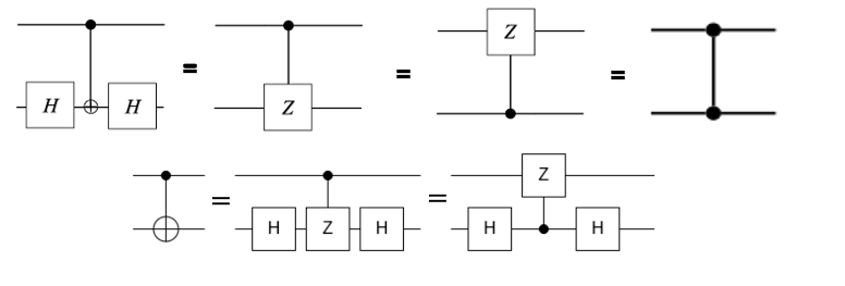
The code in Qiskit:
[11]:
qiskit_circuit = QuantumCircuit(2)

# Add (CNOT) built using equivalence with H-CZ-H
qiskit_circuit.h(1)
qiskit_circuit.cz(0, 1)
qiskit_circuit.h(1)
# Draw the circuit
qiskit_circuit.draw()
[11]:
q_0: ──────■──────
     ┌───┐ │ ┌───┐
q_1: ┤ H ├─■─┤ H ├
     └───┘   └───┘
Then we call the converter like the previous example
[12]:
state = Statevector.from_int(0, 2**3)
state = state.evolve(qiskit_circuit)

qiskit_converter = QiskitConverter(backend_name="SLOS")
quantum_processor = qiskit_converter.convert(qiskit_circuit)

pcvl.pdisplay(quantum_processor, recursive=True) # the perceval processor can be displayed at this point if needed
[12]:

[13]:
input_states = [pcvl.BasicState([1, 0, 1, 0]), pcvl.BasicState([1, 0, 0, 1]), pcvl.BasicState([0, 1, 1, 0]), pcvl.BasicState([0, 1, 0, 1])]
analyzer = Analyzer(quantum_processor, input_states)
pcvl.pdisplay(analyzer)
| |1,0,1,0> | |1,0,0,1> | |0,1,1,0> | |0,1,0,1> | |
|---|---|---|---|---|
| |1,0,1,0> | 1 | 0 | 0 | 0 |
| |1,0,0,1> | 0 | 1 | 0 | 0 |
| |0,1,1,0> | 0 | 0 | 0 | 1 |
| |0,1,0,1> | 0 | 0 | 1 | 0 |
Few remarks
Controlflow operations such as measurement operator in the qiskit circuit or
qiskit.circuit.QuantumCircuit.if_testare not supported.Custom gates from Qiskit are also not supported at the moment (see Issue#201).
Only the following gates are supported:
1-Qubit gates
2-Qubits gate: CNOT
3-Qubits gate: Toffoli